How to build the Iambic Morse Keyer
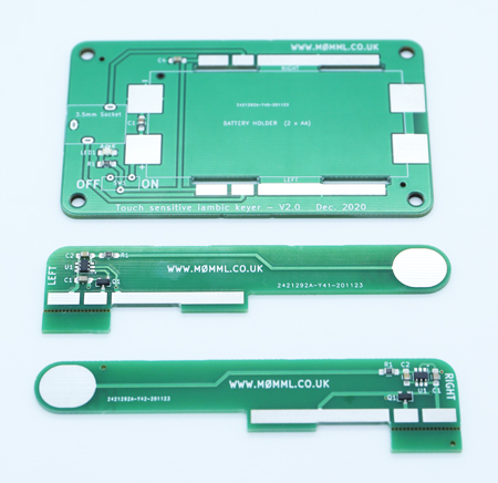
1. Start by identifying all the parts in the box. It should
comprise of the following...
Main PCB
Left PCB
Right PCB
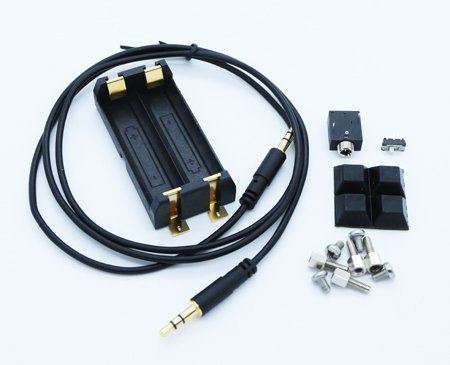
AA Battery Holder
Two position slide switch
3.5mm Stereo Connector
If you have purchased with a base, then you will also have...
Pre-drilled and tapped aluminium base
4pcs M3 x 5 screws
4pcs 5mm stand-offs
4pcs stick on rubber feet
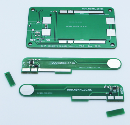
2. Break and discard the tab off each arm PCB. The piece to
break off is serrated, so a pair of snub nose pliers is best. A solid
surface could also be used, and pressure applied to the tab joint with
both thumbs whilst
gripping the top of the arm with the fingers.
3. Slide the left arm into the left slot and making sure it is seated
correctly, solder the middle of the three pads to join the two boards
together. Then using a square or other item that has a 90-degree
angle, reflow the joint if needed to make sure the arm sits at a 90-degree angle to the mainboard.
Now you can flood the adjacent two pads with solder to make a secure
joint.
Repeat for the right hand arm.
4. Next, we need to solder the battery holder. This will only fit
one way round, as there is a locating pin on one corner and a matching
hole in the main PCB. Fit the battery holder and align centrally
between the two arms. Apply heat to the metal tab in the opposite
corner of the holder to the locating pin (front left) and feed solder
into the central hole and around the edge. If enough heat
is applied, the solder will flow nicely under the tab. Repeat for
all four tabs.
5. Both the switch and stereo connector are leaded through hole
components and can be soldered in either order. I find that soldering
just one pin of each device first, allows you to check that the
component is straight and tight to the board, before soldering the
remaining pins.
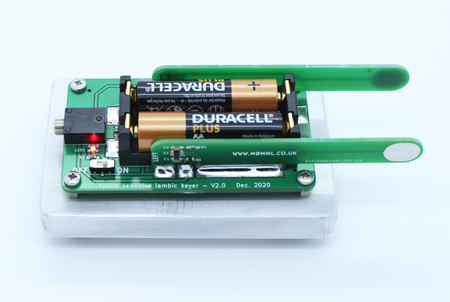
6. Pop in the two supplied AA batteries in the correct orientation, as
marked inside the battery holder. If inserted incorrectly, you may
release the magic smoke from the touch sensitive chips on each arm, as
there is no reverse polarity protection.
Check that the red power LED illuminates when the switch is slid to the
ON position. If the LED does not come on, immediately slide the
switch OFF and check the batteries are inserted correctly.
7. It's probably wise to test the key at this point, before mounting to
a base or encasing it. Read your radio manual for information on
how to do this.
On the Yaesu 991a, menu option 012 I left as the default option "ELEKEY
B". Change the MODE to CW-LSB or CW-USB. Once I had set the
mode, I could set the KEYER option to ON in the menu options. I
also left BK-IN set to OFF, so that it did not transmit whilst testing.
Connect the stereo audio cable between the keyer and the radio, switch
on using the slide switch and test both paddles in turn by touching with
your thumb or finger.
8. Mounting the keyer to the metal base is straight forward. Screw
the four stand-off posts in to the metal base until they are hand tight. Use a socket
set, spanner or pliers just to nip them up. Do not over tighten as
the threaded portion may shear off!
Place the keyer on top of the posts and align the four holes.
Loosely screw in the four screws in turn and once all in, nip them up,
again not too tight.
9. A 3D printed cover may be available, or you can print your own using
the .STL file from the link below...
www.timothyduke.com/radio/images/morsecover.stl
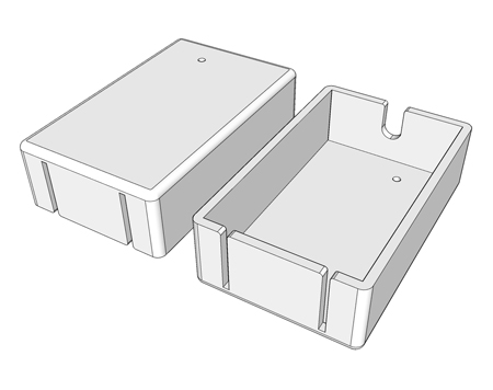
The cover slides down over the arms and 3.5mm connector and is a snug
fit.
Congratulations, your Iambic key is now complete. Enjoy and I hope
to see you on the airwaves.
Tim de M0MML